Product Description
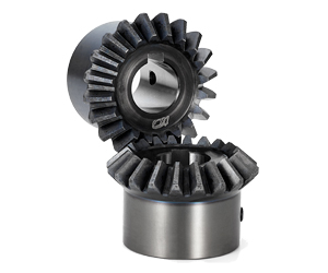
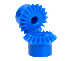
Hypoid Gear Best Quanlity Miter Spiral Wheel Set 90 Degree Forged Plastic Sintered Stainless Steel Metal Helical Tooth CHINAMFG for Test Machine Spacer Hypoid Gear
Application of Hypoid Gear
Hypoid gears are a type of gear that are used to transmit rotational power, or torque, between 2 shafts at right angles. They are similar to spiral bevel gears, but the pinion axis is offset from the gear axis. This offset creates a larger contact area between the teeth, which results in smoother operation and less noise. Hypoid gears are also more efficient than spiral bevel gears, and they can transmit more torque.
Hypoid gears are used in a wide variety of applications, including:
- Automotive: Hypoid gears are used in the rear axles of most cars and trucks. They are also used in some front-wheel drive vehicles.
- Machine tools: Hypoid gears are used in machine tools, such as lathes, mills, and grinders.
- Robotics: Hypoid gears are used in robots to transmit motion and power.
- Aerospace: Hypoid gears are used in aircraft and spacecraft to control movement and stability.
- Industrial machinery: Hypoid gears are used in a wide variety of industrial machinery, such as conveyor belts, elevators, and cranes.
- Consumer products: Hypoid gears are used in a variety of consumer products, such as power tools, appliances, and toys.
The specific application of a hypoid gear will depend on the requirements of the system in which it is being used. For example, gears used in an engine need to be able to withstand high loads and temperatures, while gears used in a robot need to be able to move quickly and precisely.
Hypoid gears are made from a variety of materials, including steel, aluminum, and bronze. The choice of material will depend on the application and the required properties of the gear. For example, steel gears are typically used in high-load applications, while aluminum gears are used in applications where weight is a concern.
Hypoid gears are manufactured using a variety of methods, including casting, machining, and powder metallurgy. The manufacturing method will depend on the size, complexity, and quantity of gears being produced.
Hypoid gears are a critical component in many systems and applications. They are available in a wide variety of sizes, materials, and manufacturing methods to meet the needs of a variety of applications.
Here are some of the advantages of using hypoid gears:
- Smoother operation
- Less noise
- More efficient
- Can transmit more torque
Here are some of the disadvantages of using hypoid gears:
- More expensive than other types of gears
- More complex to manufacture
- Can be more difficult to lubricate
Overall, hypoid gears are a versatile and efficient type of gear that can be used in a wide variety of applications.
A hypoid is a type of spiral bevel gear whose axis does not intersect with the axis of the meshing gear. The shape of a hypoid gear is a revolved hyperboloid (that is, the pitch surface of the hypoid gear is a hyperbolic surface), whereas the shape of a spiral bevel gear is normally conical.
| Application: | Motor, Electric Cars, Motorcycle, Machinery, Marine, Toy, Agricultural Machinery, Car |
|---|---|
| Hardness: | Hardened Tooth Surface |
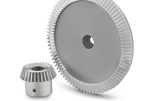
| Gear Position: | Internal Gear |
| Manufacturing Method: | Cast Gear |
| Toothed Portion Shape: | Worm Gear |
| Material: | Stainless Steel |
| Samples: |
US$ 9999/Piece
1 Piece(Min.Order) | |
|---|
What are the factors to consider when selecting miter gears for an application?
When selecting miter gears for an application, several factors need to be taken into consideration to ensure optimal performance and compatibility. Here are some key factors to consider:
1. Load Requirements:
Determine the magnitude and type of load that the miter gears will be subjected to. Consider factors such as torque, speed, and direction of rotation. This information helps in selecting miter gears with the appropriate load capacity and tooth strength to handle the application’s requirements.
2. Gear Ratio:
Identify the desired gear ratio, which is the ratio of the number of teeth between the input and output gears. The gear ratio determines the speed and torque relationship between the gears. Select miter gears with a gear ratio that meets the specific speed and torque requirements of the application.
3. Accuracy and Precision:
Determine the required level of accuracy and precision for the application. Certain applications, such as precision instruments or robotics, may require miter gears with high precision and low backlash to ensure accurate motion transmission.
4. Space Constraints:
Evaluate the available space for the miter gears within the system. Consider the gear dimensions, shaft orientations, and clearance requirements. Choose miter gears that can fit within the available space while still allowing for proper meshing and alignment.
5. Noise and Vibration:
Consider the acceptable levels of noise and vibration for the application. Spiral bevel gears, for example, are known to reduce noise and vibration compared to straight bevel gears. Select miter gears with suitable tooth profiles and designs to minimize noise and vibration if required.
6. Lubrication and Maintenance:
Assess the lubrication and maintenance requirements of the miter gears. Some miter gears may require specific lubrication methods or periodic maintenance. Consider the ease of access for lubrication and maintenance tasks when selecting miter gears.
7. Environmental Factors:
Take into account the environmental conditions in which the miter gears will operate. Factors such as temperature extremes, moisture, dust, chemicals, or exposure to corrosive substances can impact gear performance. Choose miter gears that are suitable for the specific environmental conditions of the application.
8. Cost and Availability:
Consider the cost and availability of the miter gears. Evaluate the overall value proposition, including the initial cost, long-term maintenance costs, and the availability of spare parts. Balance the cost factor with the desired performance and reliability.
By considering these factors, engineers and designers can select miter gears that are well-suited for the application’s requirements, ensuring efficient and reliable operation.
“`
Can you provide examples of machinery that utilize miter gears?
Miter gears find application in various machinery and mechanical systems. Here are some examples of machinery that utilize miter gears:
1. Power Tools:
Miter saws and compound miter saws commonly use miter gears to transmit power at a 90-degree angle, allowing for precise cutting angles and bevels.
2. Robotics:
Miter gears are frequently used in robotic systems to transmit motion between joints and enable accurate movement and positioning.
3. Automotive Systems:
Miter gears are employed in automotive applications such as differentials, steering systems, and transfer cases to transmit power and change drive direction.
4. Printing Machinery:
Miter gears are utilized in printing presses to transfer power and change the orientation of rotating cylinders, enabling proper paper feeding and print registration.
5. Aerospace Systems:
Miter gears are found in aerospace applications like aircraft landing gear systems, where they are used to transmit power and change the direction of motion.
6. Medical Devices:
Medical equipment, such as surgical robots and imaging devices, may incorporate miter gears to achieve compact designs and precise motion transmission.
7. Industrial Machinery:
Miter gears are used in various industrial machinery, including conveyors, packaging equipment, and assembly line systems, to change the direction of motion and transmit power efficiently.
8. Construction Equipment:
Construction machinery, such as excavators and cranes, may employ miter gears in their rotating mechanisms to transmit power and change the direction of motion.
9. Marine Systems:
Miter gears are utilized in marine applications like propulsion systems and steering mechanisms to transmit power and change the direction of rotation.
10. HVAC Systems:
Heating, ventilation, and air conditioning (HVAC) systems may incorporate miter gears in their fan assemblies to change the direction of rotation and transmit power efficiently.
These are just a few examples of machinery that utilize miter gears. The versatility and space-saving characteristics of miter gears make them suitable for a wide range of applications across various industries.
How do miter gears differ from other types of gears?
Miter gears possess distinct characteristics that set them apart from other types of gears. Here’s a detailed explanation:
1. Shape and Tooth Orientation:
Miter gears have a conical shape with teeth cut at a 90-degree angle to the gear’s face. This differs from other gears, such as spur gears or helical gears, which have cylindrical or helical tooth profiles. The conical shape of miter gears allows them to transmit motion between intersecting shafts at a right angle.
2. Shaft Arrangement:
Miter gears are specifically designed for transmitting power and motion between intersecting shafts. They are suitable for applications where the shafts intersect at a 90-degree angle. In contrast, other types of gears, such as spur gears or worm gears, are typically used for parallel or non-intersecting shafts.
3. Direction of Rotation:
One of the primary differences lies in the capability of miter gears to change the direction of rotation. By meshing two miter gears, the input rotational motion can be redirected at a 90-degree angle. This is in contrast to other gears that primarily transmit motion in the same direction as the input.
4. Speed Reduction or Increase:
Miter gears can be used to achieve speed reduction or increase by varying the number of teeth on the gears or combining them with other gears. This allows for adjusting the rotational speed to match the desired output speed. In contrast, other gears may have different mechanisms, such as helical gears with inclined teeth for smooth and quiet operation or worm gears for high speed reduction.
5. Compact Design:
Miter gears are known for their compact design. The intersecting shafts and the conical shape of the gears enable efficient power transmission while occupying minimal space. This compactness is particularly advantageous in applications where size and weight constraints are critical factors.
6. Application-Specific Use:
Miter gears find specific applications where the requirement is to change the direction of rotation between intersecting shafts at a 90-degree angle. They are commonly used in power transmission systems, automotive differentials, mechanical clocks, robotics, printing machinery, woodworking tools, camera lenses, and other devices.
In summary, miter gears differ from other types of gears in terms of their conical shape, suitability for intersecting shafts at a 90-degree angle, ability to change the direction of rotation, capability for speed reduction or increase, compact design, and application-specific use. These unique characteristics make miter gears valuable in various mechanical systems where specific motion transmission requirements need to be met.


editor by CX 2023-11-01