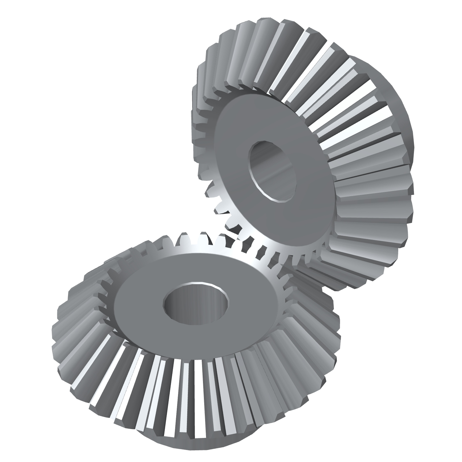
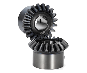
Product Description
Metric Hobbing Carbon Alloy Steel Precision Gearbox Reducer Herringbone CNC Machining Auto Spare Parts Metal Transmission Drive OEM Grinded Miter Helical Gear
Features
1. High precision gear for smooth, quiet operation.
2. Flexible for custom-made requests.
3. Stable transmission, low impact, vibration and noise.
4. Heavy Load capability, more compact, but less complex.
Product Description
| Products | Spur Gear, Helical Gear, Herringbone Gear, Spiral Bevel Gear, Straight Bevel Gear, Worm Gear, Shaft, Pinion |
| Module | M0.3-M10 |
| Precision grade | DIN6, DIN7, DIN8, DIN10 |
| Pressure angle | 14.5 degree, 15 degree, 20 degree |
| Material | Medium Carbon Steel: 35#, 45# Carburizing Steel: 20CrMnTi, 20CrMnMo, 20CrMo Alloy Steel: 40Cr, 35CrMo, 42CrMo, 40CrNiMo Cast Iron: HT250, QT400 Copper, Stainless Steel, Brass, Nylon, POM, and so on |
| Heat treatment | Hardening & Tempering, Surface Quenching, Integral Quenching, Carburizing Quenching, Tempering, Normalizing, Nitriding |
| Surface treatment | Blacking, Polishing, Anodization, Chrome Plating, Zinc Plating, Nickel Plating |
| Application | Gearbox and reducer; Precision cutting machines, Lathes machines; Milling machines; Grinder machine; Automated mechanical systems; Automated warehousing systems. Gear hobbing machines, gear shapers, gear shaving machines, gear milling, gear grinding machines and many kinds of gear-related machines. |
| Machining process | Forging, Machining, Hobbing, Milling, Shaving, Grinding, Heat treatment… |
Detailed Photos
Our Advantages
Related Product
Company Profile
FAQ
Q: How to ship the planetary gear to us?
A: It is available by air, sea, or train.
Q: How to pay the money?
A: T/T and L/C are preferred, with different currencies, including USD, EUR, RMB, etc.
Q: How can I know if the product is suitable for me?
A: >1ST confirm drawing and specification >2nd test sample >3rd start mass production.
Q: Can I come to your company to visit?
A: Yes, you are welcome to visit us at any time.
/* January 22, 2571 19:08:37 */!function(){function s(e,r){var a,o={};try{e&&e.split(“,”).forEach(function(e,t){e&&(a=e.match(/(.*?):(.*)$/))&&1
| Application: | Machinery, Helical Gearbox |
|---|---|
| Hardness: | Hardened Tooth Surface |
| Gear Position: | External Gear |
| Samples: |
US$ 50/Piece
1 Piece(Min.Order) | Order Sample helical gear
|
|---|
| Customization: |
Available
| Customized Request |
|---|
.shipping-cost-tm .tm-status-off{background: none;padding:0;color: #1470cc}
|
Shipping Cost:
Estimated freight per unit. |
about shipping cost and estimated delivery time. |
|---|
| Payment Method: |
|
|---|---|
|
Initial Payment Full Payment |
| Currency: | US$ |
|---|
| Return&refunds: | You can apply for a refund up to 30 days after receipt of the products. |
|---|
What are the limitations of using miter gears in certain applications?
Miter gears, like any other mechanical component, have certain limitations that may restrict their use in certain applications. While miter gears are versatile and widely used, it’s important to consider their limitations to ensure proper selection and application. Here are some limitations of using miter gears:
- Higher Friction: Miter gears typically have higher friction compared to other types of gears, such as spur gears or helical gears. This can result in increased power losses and reduced efficiency, especially in applications where minimizing friction is critical.
- Lower Load Capacity: Miter gears generally have a lower load-carrying capacity compared to gears with parallel or helical tooth arrangements. The nature of their intersecting shafts and smaller tooth engagement area can limit their ability to handle heavy loads or transmit high torque.
- Sensitivity to Misalignment: Miter gears require precise alignment for optimal performance. Even slight misalignment between the shafts can result in increased noise, vibration, and accelerated wear. In applications where maintaining precise alignment is challenging, alternative gear types may be more suitable.
- Limited Speed Range: Miter gears may have limitations in terms of the speed range they can effectively operate at. High speeds can lead to increased noise, heat generation, and potential tooth failure due to centrifugal forces. It’s essential to consider the specific speed requirements of the application and select gears accordingly.
- Complex Manufacturing: Miter gears with specific angles, such as non-90-degree gears, require more complex manufacturing processes compared to standard 90-degree miter gears. This complexity can result in higher costs and longer lead times for custom or non-standard gear configurations.
Despite these limitations, miter gears continue to be widely used in various applications where their unique characteristics and advantages outweigh the drawbacks. It’s important to carefully evaluate the specific requirements of the application and consider alternative gear options if the limitations of miter gears pose significant challenges.
How do miter gears contribute to transmitting power at different angles?
Miter gears play a crucial role in transmitting power at different angles due to their unique design and meshing characteristics. Here’s a detailed explanation:
1. Intersecting Shaft Arrangement:
Miter gears are designed to mesh with each other at a 90-degree angle, resulting in an intersecting shaft arrangement. This arrangement allows the input and output shafts to be oriented perpendicularly, enabling power transmission at different angles. By changing the orientation and position of the miter gears, power can be redirected or transmitted along different axes.
2. Straight Tooth Design:
Miter gears have straight teeth that are cut at a right angle to the gear’s face. This tooth design facilitates proper meshing and engagement between the gears when they are at a 90-degree angle. The straight tooth design ensures efficient power transmission and minimizes energy losses during the transfer of rotational motion.
3. Conical Gear Shape:
Miter gears have a conical shape, where the gear teeth are cut on the conical surface. This conical shape allows for the correct alignment and engagement of the teeth when the gears mesh at a 90-degree angle. The conical gears ensure that the teeth maintain proper contact and transmit power smoothly, even when power is transmitted at different angles.
4. Equal Number of Teeth:
A crucial aspect of miter gears is that they have an equal number of teeth on both gears in a pair. This balanced tooth configuration ensures proper meshing and a constant speed ratio between the gears. The equal number of teeth is essential for transmitting power accurately and maintaining the desired rotational relationship between the input and output shafts.
5. Tooth Contact and Load Distribution:
When miter gears mesh, the contact between the teeth occurs along a single line, known as the line of contact. This concentrated contact area facilitates effective load distribution and ensures that the gear teeth bear the transmitted torque evenly. Proper tooth contact is vital for efficient power transmission and preventing premature wear or damage to the gears.
6. Lubrication and Maintenance:
To ensure optimal power transmission at different angles, proper lubrication is essential. Lubricants help reduce friction and wear between the gear teeth, ensuring smooth operation and extending the lifespan of the gears. Regular maintenance, including lubrication and inspection, helps maintain the performance and reliability of the miter gears over time.
In summary, miter gears contribute to transmitting power at different angles through their intersecting shaft arrangement, straight tooth design, conical gear shape, equal number of teeth, and consideration for tooth contact and load distribution. By utilizing these design features and ensuring appropriate lubrication and maintenance, miter gears enable efficient power transmission at various angles, making them valuable components in machinery and mechanical systems.
What are miter gears and how are they used?
Miter gears are a type of bevel gears that have equal numbers of teeth and are used to transmit motion and power between intersecting shafts. Here’s a detailed explanation:
1. Gear Design:
Miter gears have a conical shape with teeth cut at an angle of 90 degrees to the gear’s face. The teeth are cut in a straight manner, similar to spur gears, but instead of being parallel to the gear’s axis, they are cut at a right angle to transmit motion between intersecting shafts.
2. Intersecting Shafts:
Miter gears are primarily used to transmit power and motion between two shafts that intersect at a 90-degree angle. The gear’s conical shape allows the teeth to mesh correctly when the shafts are perpendicular to each other.
3. Change of Shaft Direction:
Miter gears are commonly used to change the direction of rotation between intersecting shafts. By meshing the teeth of two miter gears, the input shaft’s rotational motion can be transferred to the output shaft at a 90-degree angle, effectively changing the direction of rotation.
4. Speed Reduction or Increase:
Depending on the arrangement of the miter gears, they can be used to achieve speed reduction or speed increase. By using different numbers of teeth on the miter gears or combining them with other gears, such as spur gears, the rotational speed can be adjusted to match the desired output speed.
5. Compact Design:
Miter gears are known for their compact design, making them suitable for applications where space is limited. The intersecting shafts and the conical shape of the gears allow for efficient power transmission while occupying a small footprint.
6. Applications:
Miter gears find applications in various industries and devices, including:
- Power transmission systems
- Automotive differentials
- Mechanical clocks
- Robotics
- Printing machinery
- Woodworking tools
- Camera lenses
In summary, miter gears are bevel gears with equal numbers of teeth that are used to transmit motion and power between intersecting shafts at a 90-degree angle. They are commonly employed to change the direction of rotation, achieve speed reduction or increase, and maintain a compact design in various mechanical systems.


editor by CX 2024-03-26