Product Description
Starshine Drive K Series Helical -Bevel Geared Motor
Features:
-High efficiency: 92%-93%;
-Vertical output, compact structure, hard tooth surface , large output torque, low noise and long service life.
-High precision: the gear is made of high-quality alloy steel forging, carbonitriding and hardening treatment, grinding process to ensure high precision and stable running.
-High interchangeability: highly modular, serial design, strong versatility and interchangeability.
Technical parameters
| Ratio | 5.36-197.37 |
| Input power | 0.12-200KW |
| Output torque | 10-62800N.m |
| Output speed | 7-415rpm |
| Mounting type | Foot mounted, foot mounted with CHINAMFG shaft, output flange mounted, hollow shaft mounted, B5 flange mounted with hollow shaft, foot mounted with hollow shaft, B14 flange mounted with hollow shaft, foot mounted with splined hole, foot mounted with shrink disk, hollow shaft mounted with anti-torque arm. |
| Input Method | Flange input(AM), shaft input(AD), inline AC motor input, or AQA servo motor |
| Brake Release | HF-manual release(lock in the brake release position), HR-manual release(autom-atic braking position) |
| Thermistor | TF(Thermistor protection PTC thermisto) TH(Thermistor protection Bimetal swotch) |
ABOUT CHINAMFG DRIVE
ZheJiang CHINAMFG Drive Co.,Ltd(Starshine) have a strong technical force with over 350 employees at present, including over 30 engineering technicians, 30 quality inspectors, covering an area of 80000 square CHINAMFG and kinds of advanced processing machines and testing equipments. We have a good foundation for the industry application development and service of high-end speed reducers & variators owning to the provincial engineering technology research center,the lab of gear speed reducers, and the base of modern R&D.
Our products are widely used in ceramic industry, glass industry, woodworking machinery , high voltage switch, food & beverage, packaging & printing, Storage & logistics, hoisting & transportation facilities…etc , and CHINAMFG technically provide the professional product & service for the medium and high-end customers, and our gearboxes are best-selling in domestic, and even in abroad , such as in Europe, North America, South America, Middle East, South Asia, Southeast Asia, Africa…etc.
In the future , CHINAMFG will hold the creed of “serving customer, diligence & simplicity, self-criticism, innovation, honesty, teamwork”, and the concept of “quality creates value” to focus on the customers’ requirements and provide them the competitive transmission solution and create value for them constantly, and make a high-end equipment manufacturing industry and create a preferred brand of replacing import products and upgrading continuously for the end users.
TEAM
QUALITY CONTROL
Quality:Insist on Improvement,Strive for CHINAMFG With the development of equipment manufacturing indurstry,customer never satirsfy with the current quality of our products,on the contrary,wcreate the value of quality.
Quality policy:to enhance the overall level in the field of power transmission
Quality View:Continuous Improvement , pursuit of excellence
Quality Philosophy:Quality creates value
3. Incoming Quality Control
To establish the AQL acceptable level of incoming material control, to provide the material for the whole inspection, sampling, immunity. On the acceptance of qualified products to warehousing, substandard goods to take return, check, rework, rework inspection; responsible for tracking bad, to monitor the supplier to take corrective measures to prevent recurrence.
4. Process Quality Control
The manufacturing site of the first examination, inspection and final inspection, sampling according to the requirements of some projects, judging the quality change trend; found abnormal phenomenon of manufacturing, and supervise the production department to improve, eliminate the abnormal phenomenon or state
5. FQC(Final QC)
After the manufacturing department will complete the product, stand in the customer’s position on the finished product quality verification, in order to ensure the quality of customer expectations and needs.
6. OQC(Outgoing QC)
After the product sample inspection to determine the qualified, allowing storage, but when the finished product from the warehouse before the formal delivery of the goods, there is a check, this is called the shipment inspection.Check content:In the warehouse storage and transfer status to confirm, while confirming the delivery of the product is a product inspection to determine the qualified products.
PACKING
DELIVERY
| Application: | Motor, Machinery, Agricultural Machinery |
|---|---|
| Function: | Distribution Power, Change Drive Torque, Change Drive Direction, Speed Changing, Speed Reduction |
| Layout: | Corner |
| Hardness: | Hardened Tooth Surface |
| Installation: | Horizontal Type |
| Step: | Three-Step |
| Customization: |
Available
| Customized Request |
|---|
What are the limitations of using miter gears in certain applications?
Miter gears, like any other mechanical component, have certain limitations that may restrict their use in certain applications. While miter gears are versatile and widely used, it’s important to consider their limitations to ensure proper selection and application. Here are some limitations of using miter gears:
- Higher Friction: Miter gears typically have higher friction compared to other types of gears, such as spur gears or helical gears. This can result in increased power losses and reduced efficiency, especially in applications where minimizing friction is critical.
- Lower Load Capacity: Miter gears generally have a lower load-carrying capacity compared to gears with parallel or helical tooth arrangements. The nature of their intersecting shafts and smaller tooth engagement area can limit their ability to handle heavy loads or transmit high torque.
- Sensitivity to Misalignment: Miter gears require precise alignment for optimal performance. Even slight misalignment between the shafts can result in increased noise, vibration, and accelerated wear. In applications where maintaining precise alignment is challenging, alternative gear types may be more suitable.
- Limited Speed Range: Miter gears may have limitations in terms of the speed range they can effectively operate at. High speeds can lead to increased noise, heat generation, and potential tooth failure due to centrifugal forces. It’s essential to consider the specific speed requirements of the application and select gears accordingly.
- Complex Manufacturing: Miter gears with specific angles, such as non-90-degree gears, require more complex manufacturing processes compared to standard 90-degree miter gears. This complexity can result in higher costs and longer lead times for custom or non-standard gear configurations.
Despite these limitations, miter gears continue to be widely used in various applications where their unique characteristics and advantages outweigh the drawbacks. It’s important to carefully evaluate the specific requirements of the application and consider alternative gear options if the limitations of miter gears pose significant challenges.

How do you calculate the gear ratio in a miter gear assembly?
The gear ratio in a miter gear assembly can be calculated by considering the number of teeth on the gears involved. Here’s a step-by-step explanation:
1. Determine the Number of Teeth:
Identify the number of teeth on both the driving gear (input gear) and the driven gear (output gear) in the miter gear assembly. The number of teeth can usually be found in the gear specifications or by physically counting the teeth.
2. Calculate the Gear Ratio:
To calculate the gear ratio, divide the number of teeth on the driven gear (output gear) by the number of teeth on the driving gear (input gear). The formula for calculating the gear ratio is:
Gear Ratio = Number of Teeth on Driven Gear / Number of Teeth on Driving Gear
3. Simplify the Ratio (Optional):
If the resulting gear ratio is a fraction, it can be simplified to its simplest form. Divide both the numerator and the denominator by their greatest common divisor to simplify the ratio.
4. Interpret the Gear Ratio:
The gear ratio indicates the relationship between the rotational speed or angular velocity of the driving gear and the driven gear. It represents how many times the driven gear rotates for each rotation of the driving gear. For example, a gear ratio of 2:1 means that the driven gear rotates twice for every rotation of the driving gear.
5. Consider the Significance:
The gear ratio has practical implications in determining the mechanical advantage and speed reduction/amplification in a miter gear assembly. A gear ratio greater than 1 indicates a speed reduction and increased torque, while a gear ratio less than 1 indicates a speed amplification and decreased torque.
In summary, the gear ratio in a miter gear assembly is calculated by dividing the number of teeth on the driven gear by the number of teeth on the driving gear. This ratio represents the relationship between the rotational speeds of the gears and provides insights into the mechanical advantage and speed transformation in the gear assembly.
How do miter gears differ from other types of gears?
Miter gears possess distinct characteristics that set them apart from other types of gears. Here’s a detailed explanation:
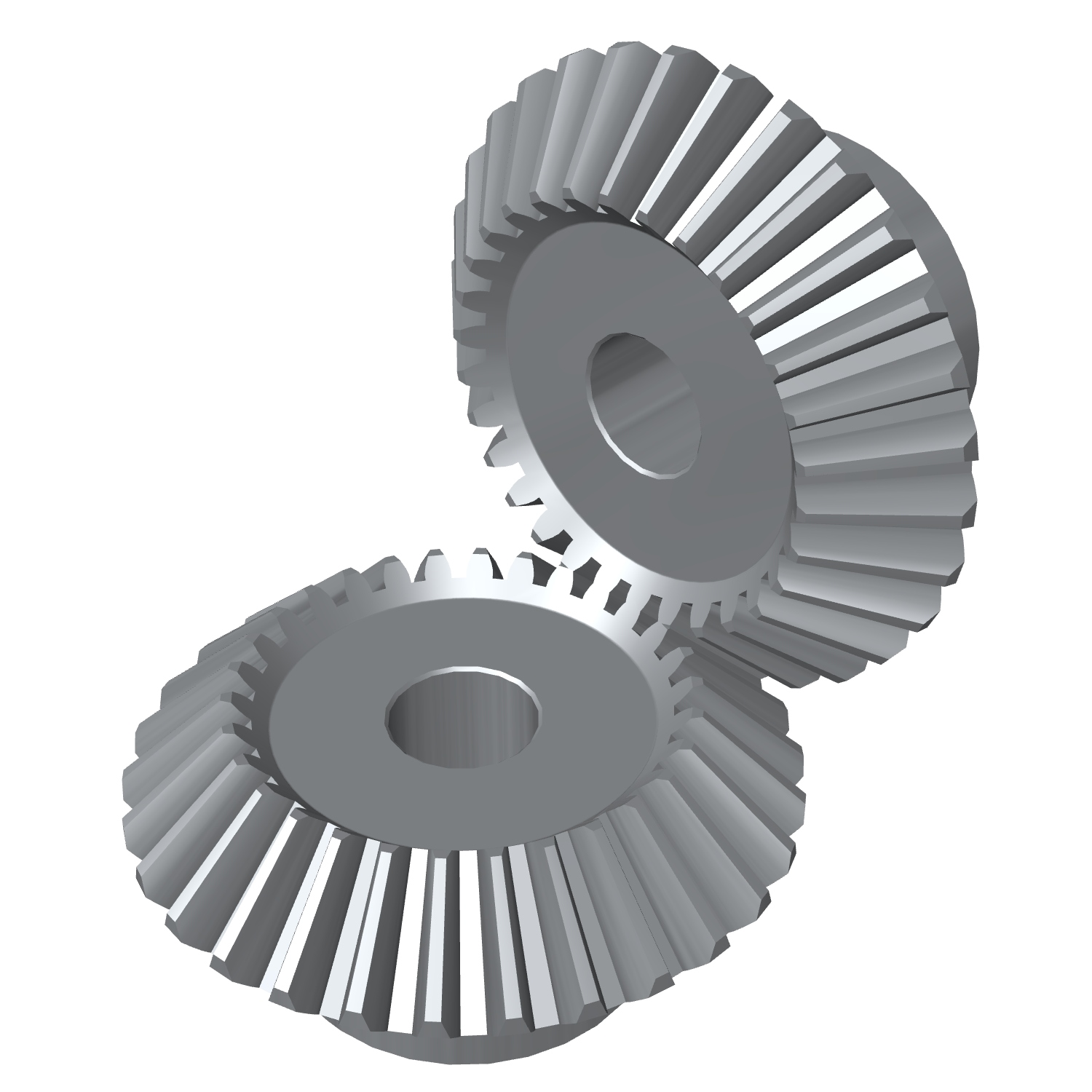
1. Shape and Tooth Orientation:
Miter gears have a conical shape with teeth cut at a 90-degree angle to the gear’s face. This differs from other gears, such as spur gears or helical gears, which have cylindrical or helical tooth profiles. The conical shape of miter gears allows them to transmit motion between intersecting shafts at a right angle.
2. Shaft Arrangement:
Miter gears are specifically designed for transmitting power and motion between intersecting shafts. They are suitable for applications where the shafts intersect at a 90-degree angle. In contrast, other types of gears, such as spur gears or worm gears, are typically used for parallel or non-intersecting shafts.
3. Direction of Rotation:
One of the primary differences lies in the capability of miter gears to change the direction of rotation. By meshing two miter gears, the input rotational motion can be redirected at a 90-degree angle. This is in contrast to other gears that primarily transmit motion in the same direction as the input.
4. Speed Reduction or Increase:
Miter gears can be used to achieve speed reduction or increase by varying the number of teeth on the gears or combining them with other gears. This allows for adjusting the rotational speed to match the desired output speed. In contrast, other gears may have different mechanisms, such as helical gears with inclined teeth for smooth and quiet operation or worm gears for high speed reduction.
5. Compact Design:
Miter gears are known for their compact design. The intersecting shafts and the conical shape of the gears enable efficient power transmission while occupying minimal space. This compactness is particularly advantageous in applications where size and weight constraints are critical factors.
6. Application-Specific Use:
Miter gears find specific applications where the requirement is to change the direction of rotation between intersecting shafts at a 90-degree angle. They are commonly used in power transmission systems, automotive differentials, mechanical clocks, robotics, printing machinery, woodworking tools, camera lenses, and other devices.
In summary, miter gears differ from other types of gears in terms of their conical shape, suitability for intersecting shafts at a 90-degree angle, ability to change the direction of rotation, capability for speed reduction or increase, compact design, and application-specific use. These unique characteristics make miter gears valuable in various mechanical systems where specific motion transmission requirements need to be met.


editor by CX 2023-10-11